Camper Van Aerodynamics with Solar Panel
External Flow Analysis for Mounting System Design
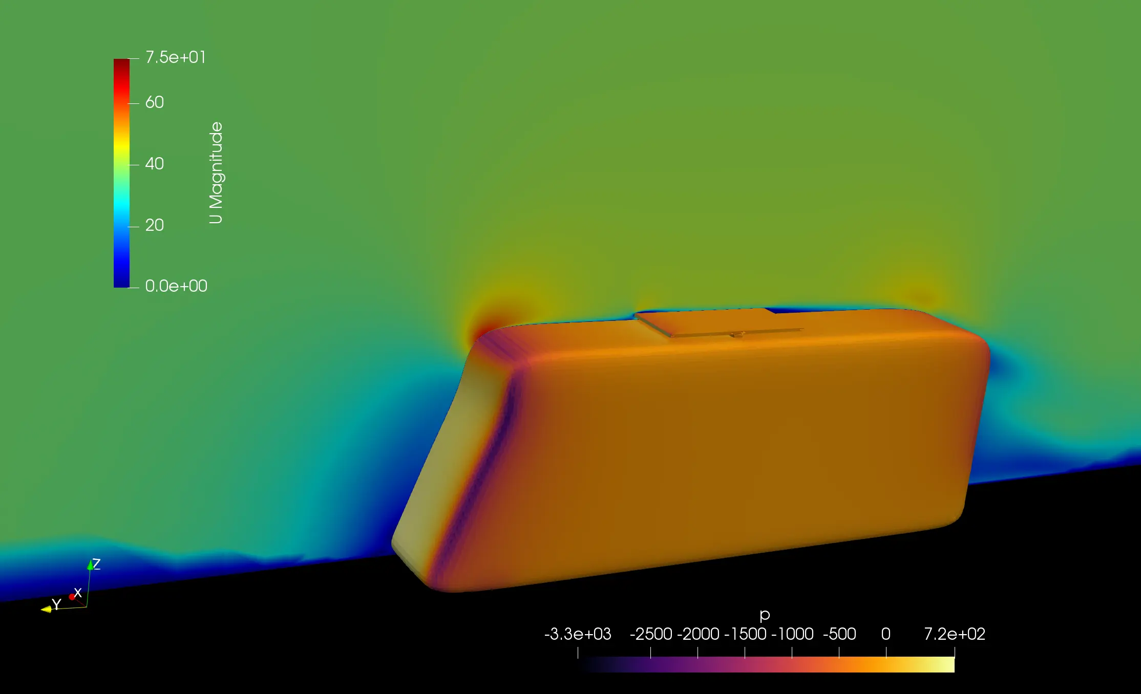
Pressure (Pa): -120 → +180
Pressure distribution and flow streamlines showing complex interactions between vehicle body and roof-mounted solar panel
Abstract
Comprehensive aerodynamic analysis of a camper van equipped with a roof-mounted solar panel system to evaluate drag characteristics, energy efficiency implications, and structural loading on the panel mounting system. This study investigates the complex flow interactions between the vehicle body and the solar panel, quantifying aerodynamic forces that inform mounting design requirements.
The simulation provides critical insights for optimizing solar panel integration while maintaining vehicle performance and ensuring structural integrity under highway operating conditions. The analysis revealed complex flow interactions with significant separation at the panel's trailing edge and vortex formation at lateral edges.
The aerodynamic analysis successfully characterized the performance impact and structural loading associated with roof-mounted solar panel installation. While the panel introduces a measurable drag penalty (11% increase in drag coefficient), the moderate aerodynamic forces are well within typical mounting system capabilities.
Metodologia
Numerical Approach
- ▸Steady-state RANS with k-omega SST turbulence model
- ▸Incompressible flow solver with SIMPLE algorithm
- ▸Moving ground simulation with rotating wheels
- ▸Refined mesh around solar panel edges for accurate force resolution
- ▸Force decomposition: normal forces, tangential forces, moment components
- ▸Comparison: baseline vehicle vs. vehicle with mounted panel
- ▸Highway cruise: 100 km/h (27.8 m/s) freestream velocity
Computational Domain
- ▸Full-scale camper van (5.4m × 2.0m × 2.7m) with detailed exterior
- ▸Roof-mounted solar panel: 1.6m × 1.0m × 0.04m positioned centrally
- ▸Virtual wind tunnel: 15L downstream, 8L upstream, 5L laterally
- ▸Computational mesh: 1.2M hexahedral elements with refinement zones
- ▸Boundary layer resolution: y+ < 1 on vehicle and panel surfaces
- ▸Refined wake region extending 10L downstream
- ▸Ground plane with moving wall boundary matching vehicle speed
Risultati e Scoperte
The analysis characterized performance impact showing manageable drag penalty with moderate aerodynamic forces well within mounting system capabilities.
Key Findings
- 1Drag coefficient increased from 0.38 to 0.42 (11% penalty)
- 2Solar panel experienced 85N upward lift force and 28N drag force
- 3Pitching moment: 42 N·m about mounting centerline
- 4Peak mounting stress: 35 MPa (within safe limits for aluminum brackets)
- 5Flow separation at panel trailing edge extending 0.8m downstream
- 6Counter-rotating vortex pairs shed from panel lateral edges
- 7Wake width increased by 12% compared to baseline
Ready to Optimize Your System?
Let's discuss how CFD analysis can deliver measurable performance improvements for your engineering challenge.
Start a Conversation